


{{goods.model}}
What is the Best CNC Router for Woodworking Relief? Tips for Professional Results

In the woodworking relief carving industry, you've likely experienced this moment: you spend hours fine-tuning every curve and every detail of a 3D relief, only to remove the workpiece and see surface chatter marks, blurred edges, and uneven bottom depths—the entire relief loses its three-dimensionality.
Relief carving is fundamentally different from conventional sheet cutting. It demands that the machine maintain extremely high-frequency Z-axis oscillation and X/Y-axis acceleration and deceleration consistently over several hours. For professional carvers who pursue ultimate detail, machine rigidity and spindle response are the decisive factors in final output quality. This article breaks down the hard requirements that wood relief carving places on a CNC router, as well as the core hardware specifications that define a CNC router wood carving machine truly suited for this application.
Ⅰ. Selection Criteria for a Wood Relief Carving CNC Router
1. Machine Bed Rigidity – The Foundation of Chatter Control
A 600×600 mm relief panel typically requires 4 to 6 hours of machining time in the finishing pass alone. Throughout that extended period, every vibration generated by the machine travels through the spindle, down to the tool tip, and ultimately leaves periodic chatter marks across the wood surface.
Chatter is the fatal flaw in relief carving. Once it appears, post-processing sanding cannot salvage the piece—because sanding away the chatter also sands away the fine details. That's why, when selecting a CNC wood router for relief work, machine bed rigidity is the very first and most non-negotiable threshold.
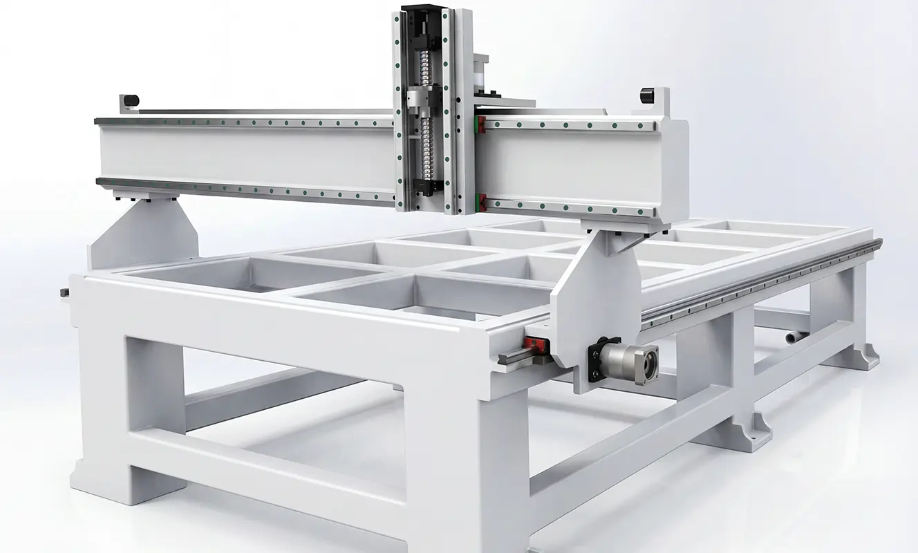
Here are three key indicators for evaluating machine bed rigidity:
- Stress-Relief Treatment of the Bed Structure
The bed must be fabricated from thick-walled square steel tubing, joined by welding, and subsequently subjected to both annealing and vibration stress-relief processes. The core purpose of this treatment is to eliminate residual internal stresses left from welding. If this step is skipped, the bed will undergo irreversible microscopic deformation over time, which will directly compromise carving accuracy in every subsequent job.
- Gantry Structural Rigidity
The gantry is the primary component that withstands cutting forces. Insufficient rigidity will allow the frame to twist and deform under heavy material removal. Quality machines incorporate thickened steel rail plates at the guideway mounting surfaces—specifically to enhance torsional resistance and ensure that the frame remains distortion-free even during aggressive roughing passes.
- Leveling Feet and Vibration-Damping Pads
Surprisingly, the source of most chatter marks isn't the machine itself—it's structural resonance. Heavy-duty leveling feet paired with rubber vibration-damping pads isolate high-frequency vibrations transmitted from the floor, preventing resonant coupling between the spindle and the frame. Industry best practice calls for at least 6 such mounting points; any fewer, and the machine simply won't run stable enough for extended relief work.
In fine surface contouring, machine bed rigidity is the ultimate determinant of results. For high-precision relief carving, lightweight structural designs simply cannot withstand the microscopic vibrations that ruin detail fidelity.
2. The Drive System – Safeguarding Accuracy Over Long Travels
The X/Y axis motion trajectory in relief carving is not a simple linear cut—it demands continuous acceleration, deceleration, and directional reversals as the tool follows the 3D surface contour. If the drive system has any backlash, each directional change introduces a momentary hesitation, resulting in a discontinuous, interrupted surface finish on the carved relief.
In professional woodworking production, the 4'×8' (approximately 1200×2400 mm) sheet size is the industry-standard worktable dimension. Machines in this size class typically employ rack-and-pinion drive systems—but not all racks are created equal.
- Helical racks are the preferred choice. Helical racks engage with a greater number of gear teeth simultaneously, delivering smoother transmission and reduced vibration compared to their straight-tooth counterparts. Straight racks produce a noticeable impact sensation during high-speed direction changes—a jarring effect that transfers directly to the tool path. Furthermore, ground-grade racks are essential; they offer a significant step up in precision and surface finish over hobbed racks, ensuring the gear meshing remains fluid and backlash-free throughout the multi-hour carving cycle.
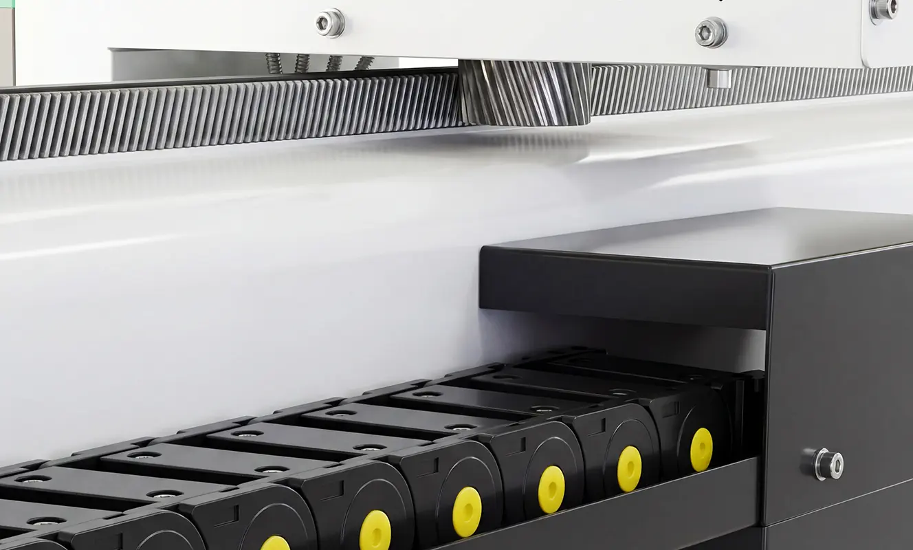
- Adjustable gear mesh clearance is a must. Mechanical transmission components inevitably experience wear over time. If the gear mesh clearance is adjustable, the machine can maintain its factory-level precision even after years of heavy use—a feature that separates long-term investments from disposable equipment.
- The Z-axis demands a ball screw. Since the Z-axis operates with continuous vertical motion, ball screws offer superior backlash control compared to rack-and-pinion systems, along with better long-term accuracy retention. The screw-driven Z-axis ensures that every upward and downward movement translates to the tool tip without lost motion or positional drift.
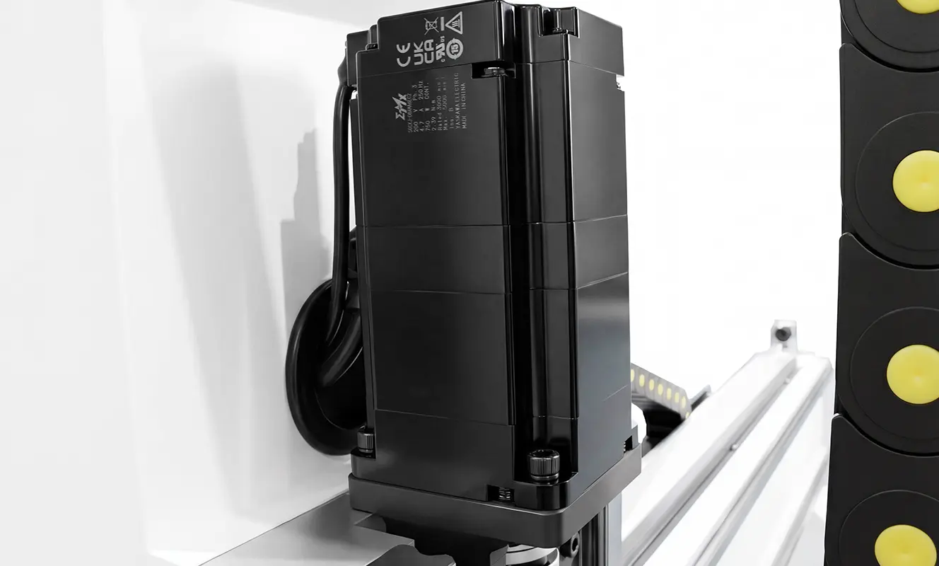
- Servo vs. stepper motors—how to choose. For the finishing stage of relief carving, servo motors are the baseline requirement. Stepper motors carry an inherent risk of step-loss during extended runtimes—and when a stepper loses steps, the entire carved surface suffers from layer shifting and misaligned contours. Closed-loop servo systems, by contrast, provide real-time position correction, maintaining perfect registration through hours of continuous operation without deviation. This distinction is one of the key markers that separates entry-level wood CNC machines from professional-grade production equipment.
3. The Spindle – Controlling Runout and Temperature Rise
The spindle is the component that directly engages in cutting. When machining reliefs, it must simultaneously satisfy two critical conditions: minimal runout and stable temperature rise.
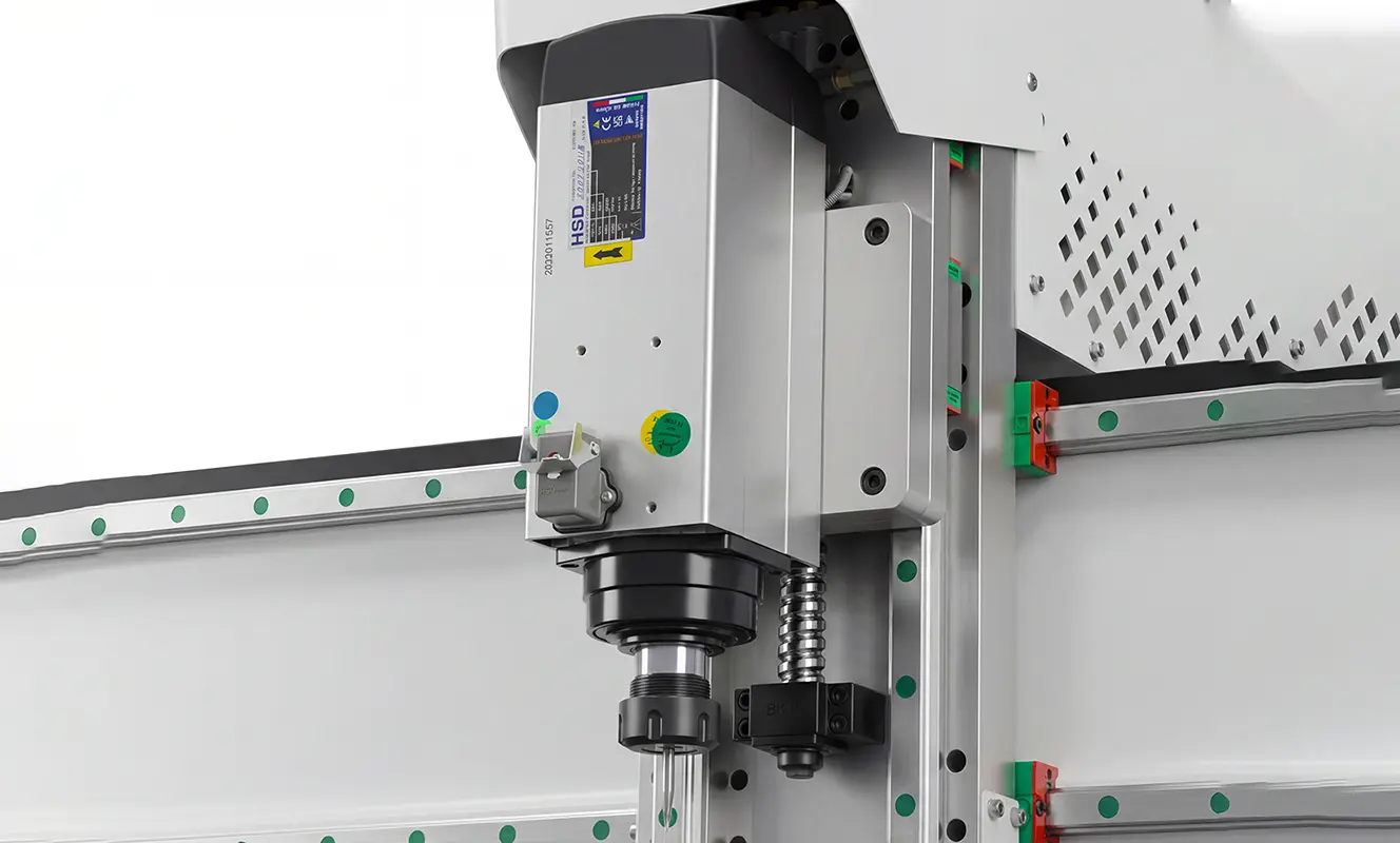
Runout: Spindle runout refers to the radial deviation of the tool tip during rotation. When runout exceeds 0.01 mm, a ball-nose cutter traversing a curved surface will leave visibly distinguishable tool marks across the finished surface—dense, fine circular patterns that resemble a sandblasted or matte finish, devoid of any refined texture.
Temperature Rise: Relief carving often runs continuously for several hours, with the spindle operating nonstop throughout. Under these conditions, an air-cooled spindle is prone to overheating. As the temperature climbs, the bearing preload shifts, causing the tool tip height to drift—and the result is an uneven bottom surface across the entire relief panel.
This is where the advantage of a water-cooled spindle becomes clear: with a stable coolant temperature, the spindle housing maintains consistent thermal equilibrium, ensuring dependable accuracy throughout the job. For a CNC wood router machine running extended multi-hour cycles, this reliability is absolutely critical.
4. The Worktable – The Key to Secure Workpiece Holding
Relief carving is performed on sheet stock, not thick blocks. During the machining process, even a 0.1 mm shift in the workpiece will scrap the entire relief. That's why the worktable must securely hold the sheet in place.
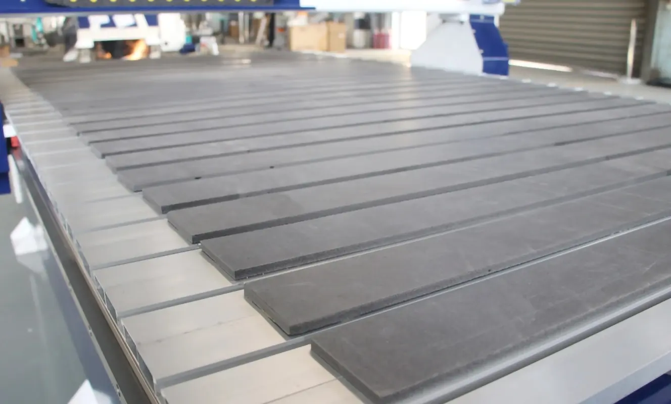
- If your workshop primarily does relief carving, a T-slot worktable is more practical. Relief carving runs long with high vibration—clamps lock the stock securely, preventing movement and ensuring precision.
- If your workshop does both relief carving and sheet cutting, a combined vacuum and T-slot table is recommended. Use vacuum hold-down for cutting and clamps for relief carving.
It's worth noting that solid wood panels have no through-holes; the vacuum seal is created by negative pressure formed in grooves routed along the perimeter of the stock. Whether these groove channels are properly designed directly determines the effectiveness of the hold-down. This detail is frequently overlooked when evaluating wood carving machines, yet it has a significant impact on real-world machining performance.
5. The Control System – Software and File Compatibility
The control system is the critical link between software and hardware. No matter how robust your machine's construction may be, if the controller isn't compatible with your CAM software, the entire system will fail to perform as intended.
Relief carving demands the generation of 3D toolpaths—and not every control system can smoothly handle the large-volume surface toolpath files that this entails. When selecting a controller, pay close attention to the following key points:
- Compatibility with mainstream CAM software: VCarve Pro, Aspire, Carveco, ArtCAM, Fusion 360, and others should all be supported through a properly configured post-processor.
- Standard G-code support with smooth large-file processing: The controller must handle standard RS-274 G-code dialects and maintain fluid, uninterrupted motion even when processing dense finishing paths with tens of millions of line segments.
- ATC logic support if you plan to use automatic tool changing: If your workflow involves tool changes mid-job, the control system must include built-in ATC (Automatic Tool Changer) logic to manage tool selection, spindle orientation, and tool-length measurement sequences.
- For beginners, prioritize systems with built-in macro commands: Features like one-click home return, one-click tool setting, and automatic workpiece referencing significantly reduce the learning curve and minimize setup errors—making daily operation simpler and more reliable.
Ⅱ. Selection Recommendations
Based on different budgets and processing requirements, several models from the CATEKCNC Spire series align well with relief carving applications, and are provided here for your reference:
Standard Configuration – Suitable for Most Relief Carving Requirements
Spire 2130-RSP-T
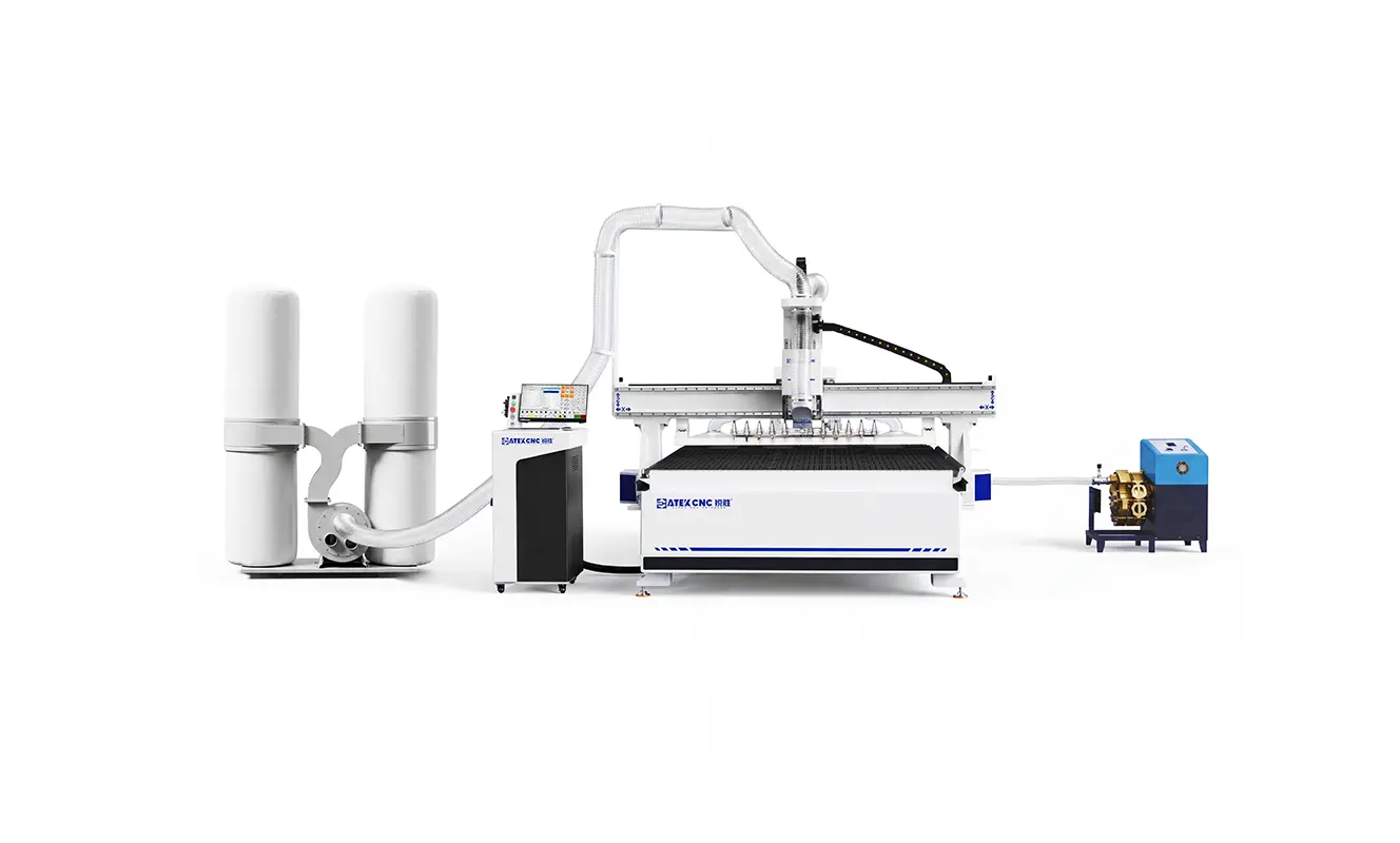
7'×10' Large Worktable + 12-Station Automatic Tool Changer – Ideal for large-format panel processing and batch production.
Core advantages:
- Bed rigidity: Thick-wall square-tube welded construction + stress-relief annealing treatment, with a 70 mm ultra-thick Z-axis mounting plate (2.5 times the industry standard).
- Transmission precision: Hiwin P-grade 30 mm guide rails + YYC helical racks + TBI ball screws, delivering greater rigidity than the standard model.
- Drive system: Taiwanese LNC 1500 W bus-type absolute servos (Y-axis dual-drive) + Shinpo gear reducers, with a traverse speed of 135 m/min.
- Spindle: HQD 9 kW automatic tool-changing air-cooled spindle, maximum speed 24,000 RPM, runout ≤0.002 mm.
- Automatic tool changer: 12-station linear tool magazine, with a 0.5-second tool change time, enabling continuous multi-process machining without stopping.
- Worktable: 15-zone, 25-port vacuum hold-down + 30 auxiliary loading rollers + automatic workpiece ejection mechanism.
Best-fit scenario: Large-format relief panels, batch production, and multi-process jobs requiring frequent tool changes.
Spire 1520-WSP
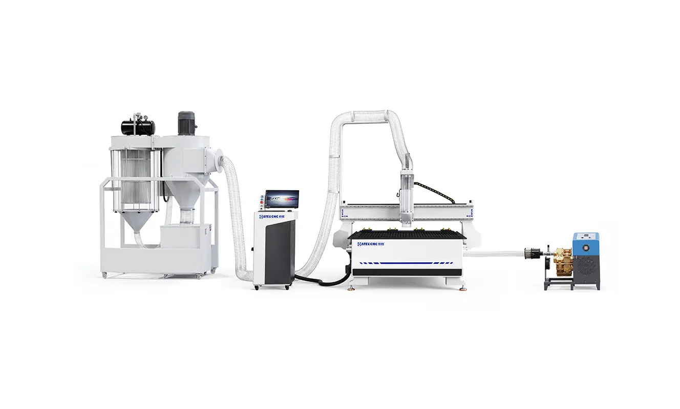
5'×6.5' Non-Standard Worktable – Specifically designed for users with limited floor space who still require a larger machining area.
Core advantages:
- Custom non-standard sizing: 1500×2000 mm worktable—narrower but longer than a 4'×8' footprint, making it ideal for workshops with space constraints.
- Bed rigidity: Thick-wall square-tube welded construction + stress-relief annealing treatment, with a 46 mm thickened anodized aluminum Z-axis mounting plate.
- Transmission precision: Hiwin P-grade 25 mm guide rails + YYC helical racks + TBI ball screws, with a repeatable positioning accuracy of ±0.01 mm.
- Drive system: CATEKCNC self-developed 750 W servo motors (Y-axis dual-drive, Z-axis with brake) + Japanese Shinpo gear reducers.
- Spindle: CATEKCNC self-developed 6 kW water-cooled spindle, maximum speed 24,000 RPM, paired with an S&A CW-5200 constant-temperature water chiller—ideal for extended continuous operation.
- Worktable: 6-zone vacuum hold-down + 3+2 pneumatic positioning.
Best-fit scenario: For users whose workshop cannot accommodate a standard 4'×8' machine but who still need to process large-format panels. If your shop space is tight, this model maximizes your machining area without expanding your facility.
High Cost-Performance Model – Designed for users with limited budgets who do not want to compromise on rigidity.
Spire 1325-WSP-SE
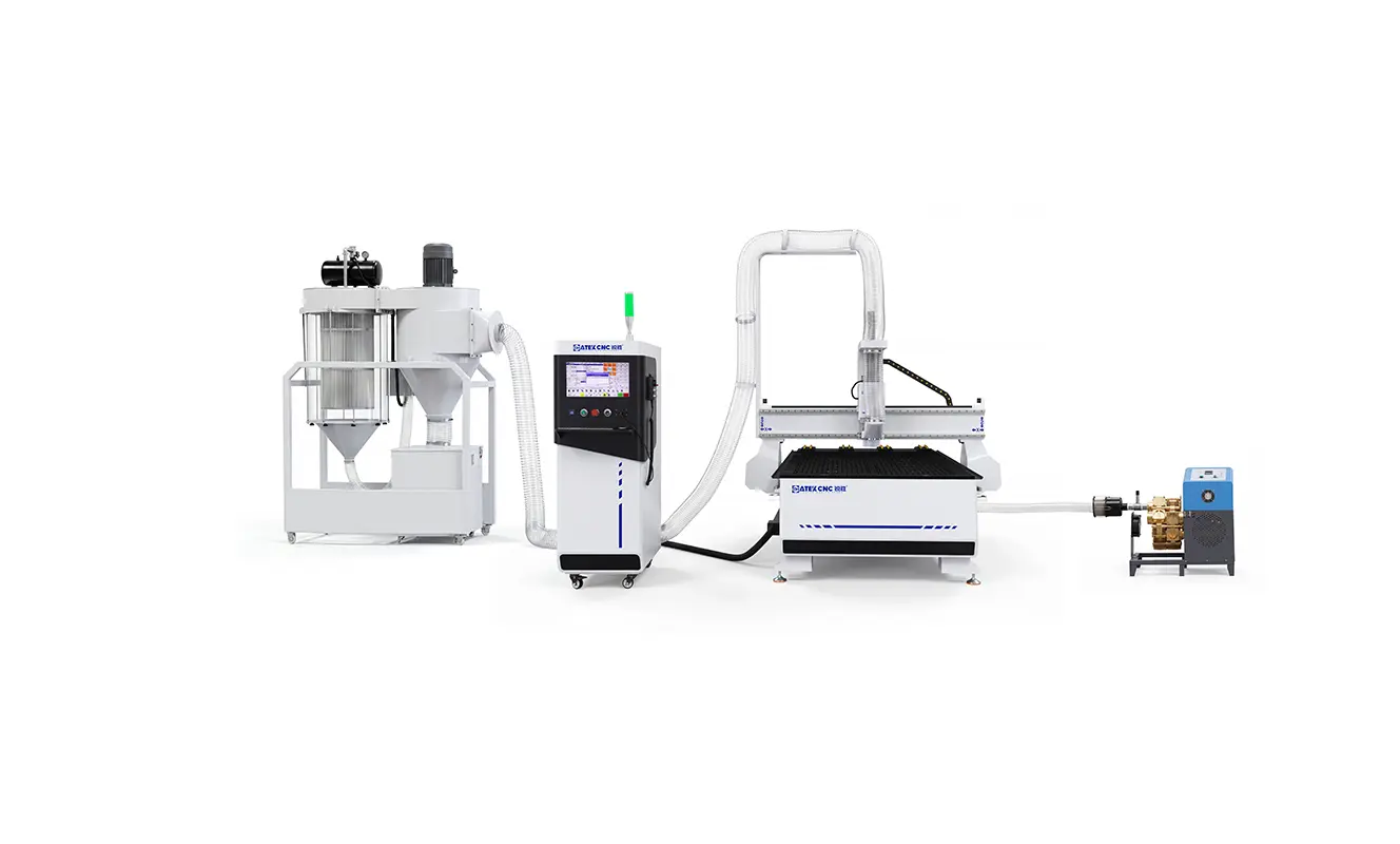
The core value of this model lies in its design for manufacturers with limited budgets who still demand quality relief carving—making it well-suited for start-up woodworking shops, small custom furniture factories, and similar operations.
The 1325-WSP-SE retains the core advantages of the Spire series—thick-wall square-tube welded bed frame, stress-relief annealing treatment, Hiwin P-grade guide rails, and YYC helical racks—and is capable of performing the following operations:
- Flat relief carving
- Sheet cutting and slotting
- Drilling and milling
- Processing of MDF, plywood, solid wood, acrylic, and other materials
All of these operations are built on the same rigid foundation as the 1325-RSP, with the bed frame and drive system maintaining the Spire series' standard level of performance.
Compared to the standard model, this version controls costs by utilizing CATEKCNC self-developed spindle and servo systems. It is equipped with a 6 kW air-cooled spindle and a 750 W servo drive system, with the Z-axis featuring a brake function. If you are price-sensitive but unwilling to compromise on fundamental rigidity, this model is well worth serious consideration.
Flexible Worktable Model – Designed for users who process a diverse range of materials.
Spire 1325-WSP
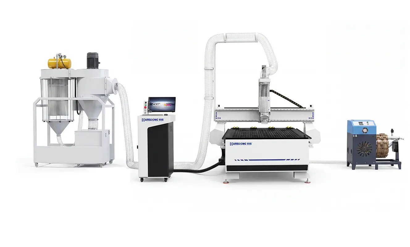
This model is designed for manufacturers who, in addition to relief carving, also have diverse daily needs such as sheet cutting, panel sizing, and slot milling. It is suitable for applications including cabinet door panels, decorative panels, and artistic reliefs.
- Stable rigid foundation: Features a thick-wall square-tube welded bed frame that has undergone stress-relief annealing treatment, paired with a 46 mm thickened anodized aluminum spindle mounting plate. Structurally, this provides vibration resistance and deformation resistance for extended relief carving operations.
- Reliable transmission and drive: All three X/Y/Z axes utilize Taiwanese Hiwin P-grade 25 mm guide rails, YYC ground helical racks, and TBI ground ball screws, paired with Japanese Yaskawa 750 W servo motors (Y-axis dual-drive) and Japanese Shimpo planetary gear reducers. This ensures repeatable positioning accuracy and smoothness during curved-surface machining.
- Spindle and worktable suited for relief carving: Equipped with an Italian HSD 6 kW air-cooled spindle with a maximum speed of 18,000 RPM and runout ≤0.005 mm, capable of meeting the demands of fine surface finishing. The worktable features a 6-zone, 24-port vacuum hold-down system, with 4+2 pneumatic positioning cylinders and auxiliary loading rollers, making sheet stock fixation and material loading both convenient.
Best-fit scenario: If you do more than just relief carving—with frequent daily cutting, sizing, and slot milling—and have a sufficient budget while seeking balanced performance, the 1325-WSP is the safest, most reliable choice.
Spire 1325-WSP-VT
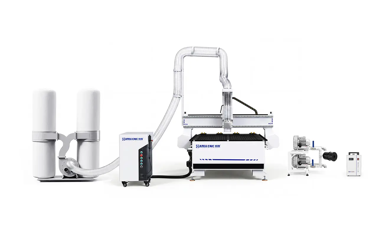
This model is specifically designed for users with diverse processing needs—featuring a dual-mode vacuum hold-down + T-slot worktable that accommodates both flat panels and irregularly shaped workpieces.
The core advantage of the 1325-WSP-VT lies in its dual-mode table design, which integrates both vacuum hold-down and aluminum-profile T-slot clamping methods. It is capable of performing the following operations:
- Large-panel relief carving: Vacuum hold-down enables rapid fixation, allowing the entire panel to be machined in a single setup.
- Irregularly shaped workpieces: T-slots paired with clamps provide flexible fixturing for non-standard stock.
- Mixed processing: Large panels secured by vacuum, with T-slot clamps assisting at the edges for added holding power.
- Small-batch, high-mix production: No need for frequent fixture changes—different workpieces can be switched over quickly.
All of these operations can be completed on a single machine, eliminating the need for two separate setups and avoiding the hassle of repeatedly switching between the vacuum pump and mechanical clamps. Paired with a 3.5 kW water-cooled spindle and a vacuum hold-down system, this model is well-suited for woodworking shops, display fabrication, model-making, and similar applications.
Ⅲ. Three Practical Tips to Elevate Relief Carving Quality
1. Separate Roughing and Finishing Passes
Many customers, after receiving their machine, try to save time by using a single tool for the entire job—from start to finish. The result is almost always the same: a rough, uneven surface and blurred details. The issue isn't the machine's precision—it's the lack of proper process segmentation.
Roughing and finishing are two distinct operations with completely different objectives. Roughing is about using a large-diameter flat end mill to quickly remove excess material, leaving a small machining allowance for the subsequent step. Finishing swaps in a ball-nose cutter that travels slowly along the curved surface, precisely shaving off the remaining stock left by the roughing pass.
| Process | Tool Type | Recommended Diameter Range | Purpose |
|---|---|---|---|
| Roughing | Flat end mill | 6–10 mm | Rapid material removal, leaving a 0.5–1.0 mm allowance |
| Finishing | Ball-nose cutter | 3–6 mm | Carve the curved surface; smaller diameter yields finer detail |
The specific diameter to use depends on the level of detail required in the relief and the size of the workpiece. For higher detail requirements, choose a smaller diameter; for larger panels or greater material removal volumes, opt for a larger diameter.
2. Set the Stepover Correctly for a Smooth Curved Surface
During finishing with a ball-nose cutter, the distance between two adjacent toolpaths is the stepover. A larger stepover means faster machining, but a rougher surface; a smaller stepover yields a smoother surface, but machining time increases exponentially.
For fine relief carving, the recommended stepover range is typically 8%–12% of the ball-nose tool diameter. For example, with a 6 mm ball-nose cutter, set the stepover between 0.5 and 0.7 mm.
For your first test carve, run several test passes on scrap material with different stepover values and compare the results side by side—this is the most direct and intuitive way to determine the optimal setting for your specific job.
3. Choose Hardwood Over Softwood
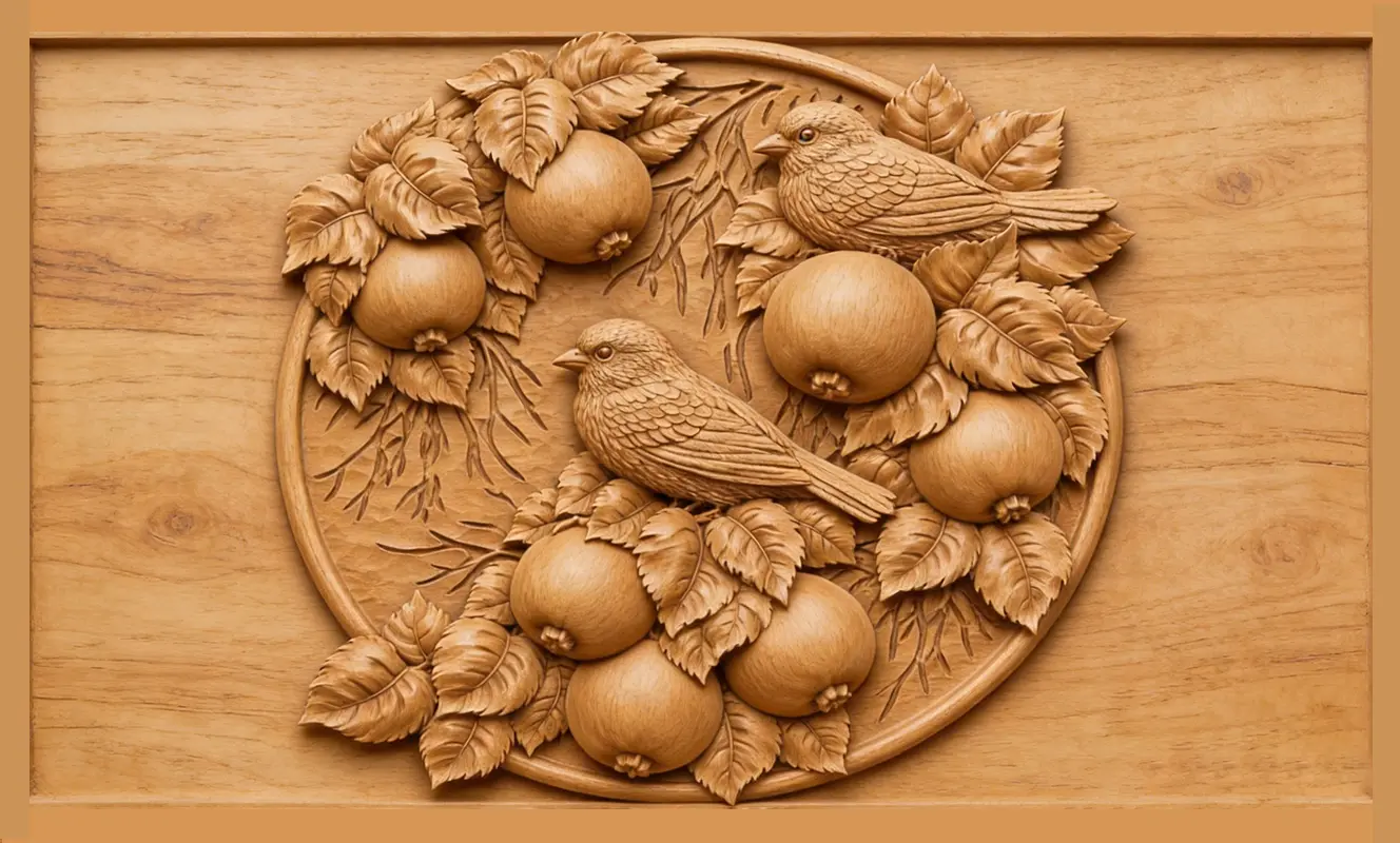
Relief carving demands crisp detail and sharp edges. Softwoods have loose, porous fibers that tend to chip and crumble during carving—sharp corners become rounded, and fine details blur into indistinct shapes.
Among commonly used hardwoods, maple, walnut, and cherry offer fine, tight grain structures with high density, delivering the best detail retention—they should be your top priorities. Oak has sufficient hardness, but its coarse, open grain can compromise fine detail performance slightly. MDF provides uniform density at a low cost, making it the ideal choice for test runs and prototyping—it's highly recommended to run a test pass on MDF before committing to your final workpiece.
As for softwoods like pine or poplar, their material is simply too soft for quality relief work. If possible, avoid them entirely—the carving results are consistently poor.
Additionally, pay close attention to the moisture content of solid wood. Before machining, ensure the lumber is conditioned to a moisture content between 6% and 10%. Wood that's too wet will shrink after carving, distorting the relief details; wood that's too dry is prone to cracking and splitting during or after the process.
Ⅳ. Quick Problem-Solving Checklist
When problems occur during machining, follow this sequence for troubleshooting:
| Problem Symptom | Possible Cause | Check Direction |
|---|---|---|
| Periodic wavy marks on the surface | Spindle runout / tool deflection / resonance | Check spindle runout report; ensure tool holder taper is clean; reduce spindle speed appropriately |
| Inconsistent depth across the panel | Uneven table surface / warped workpiece / insufficient vacuum hold-down | Check table flatness; inspect vacuum pump and hoses for air leaks |
| Blurred or lost details | Stepover too large / worn tool / spindle speed too low | Reduce stepover; replace with a new ball-nose cutter; increase spindle speed appropriately |
| Burn marks or dark streaks on the wood surface | Spindle speed too high or feed rate too slow | Reduce spindle speed or increase feed rate |
Ⅴ. FAQ
1. How do I choose the right worktable size?
Base it on your maximum regular sheet size. For 4'×8' panels, choose a 4'×8' table to carve full sheets in one setup. A smaller table requires pre-cutting, adding an extra step. A larger table increases cost and footprint—just get what's sufficient.
2. What spindle speed should I set?
For finishing with a ball-nose cutter, start at 16,000–20,000 RPM. Too high burns the wood; too low leaves a fuzzy surface. Solid wood runs slightly lower than MDF; hardwoods higher than softwoods. Best way: test on scrap.
3. What's the difference between a ball-nose cutter and a flat end mill?
A ball-nose cutter has a rounded tip that follows 3D contours smoothly, producing a clean, even surface—used for finishing. A flat end mill has a flat tip and cannot transition smoothly across curves—used for roughing to remove bulk material quickly.
4. Why separate roughing and finishing?
Roughing uses a large flat end mill to remove material quickly, leaving a 0.5–1 mm allowance for finishing. Finishing uses a small ball-nose cutter to trace the surface and produce a smooth result. Using one tool for the whole job either slows roughing or compromises finishing—losing on both ends.
Ⅵ.Conclusion
Choosing a CNC router for relief carving isn't about price or brand—it's about whether the configuration matches the demands of the job.
Relief carving requires far greater rigidity, precision, and stability than standard sheet cutting. A competent woodworking engraving machine must have a frame stiff enough to resist high-frequency vibration, spindle runout within spec, and a drive system that holds position over long runs. Only when all three are met does the machine have the hardware foundation for fine detail work.
Once the machine is in place, process technique matters just as much. Separate roughing and finishing, keep stepover in the right range, choose suitable wood—handle these at the programming and setup stage, and many surface issues never appear.
Before purchasing, clarify your needs: what materials, what sheet sizes, what precision level. Bring that information to your selection, and you'll find the best CNC machine for woodworking for your specific production scenario. For shops where relief carving is the core business, a machine that consistently delivers high-quality output is productivity itself.
CATEKCNC offers a full product line from 3-axis relief engravers to multi-process machining centers, covering wood relief needs across different scales and precision requirements.
RELATED MODELS
We recommend some related models for you...
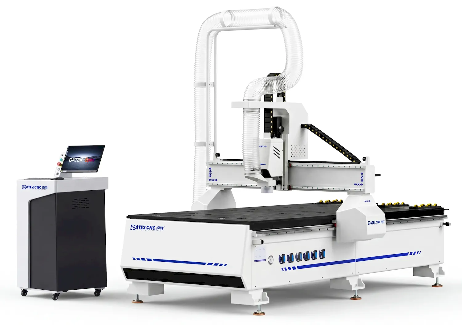
The CK-1325-WSP is a standard CNC wood router of the Spire Series. It inherits the excellent DNA of the Spire range, is fitted with renowned components including Yaskawa servo motors, HSD spindles and Schneider electric parts, and comes with the exclusive VIP services of the Spire Series.
$7,280.00~$13,980.00
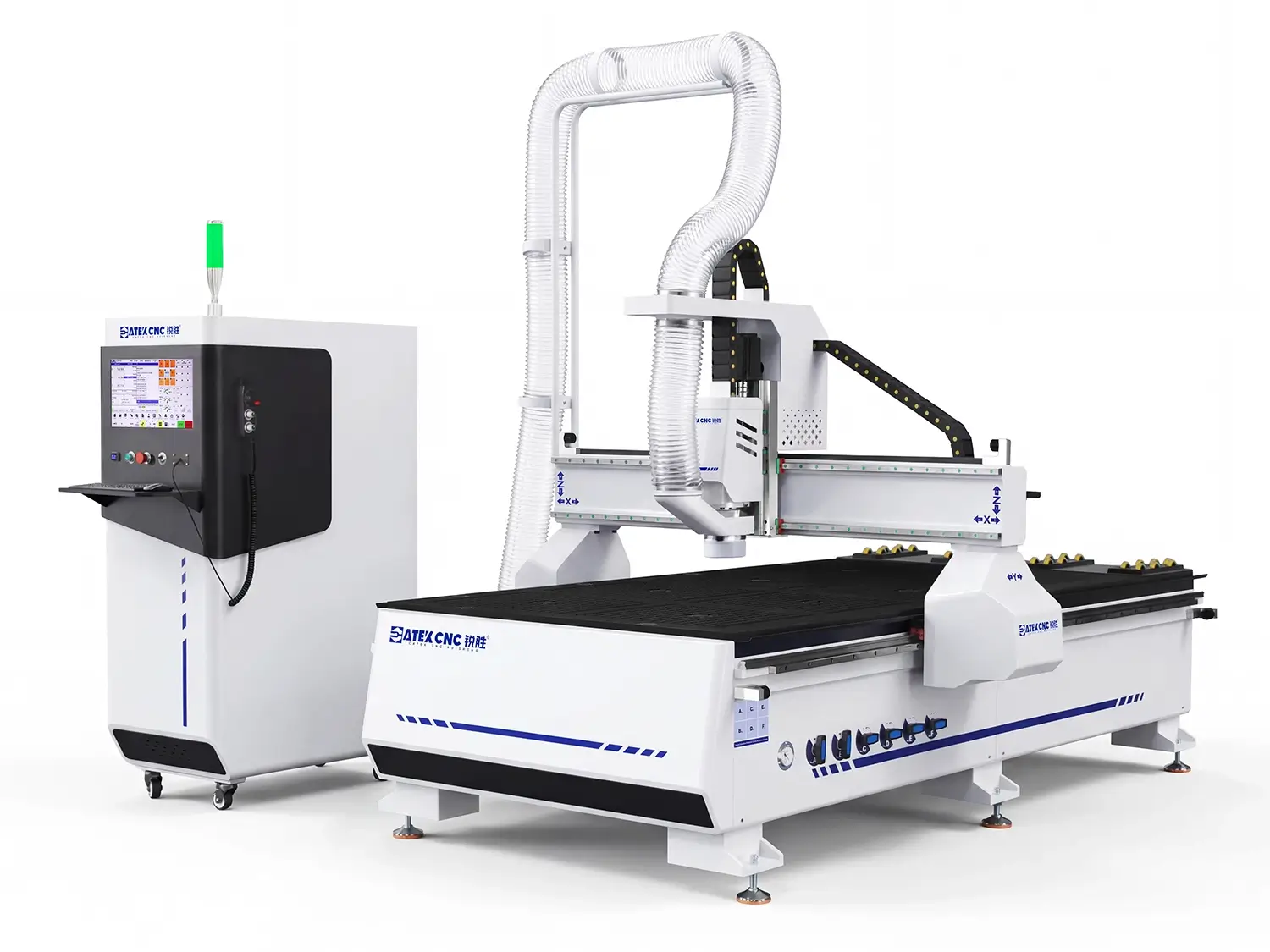
This affordable 4x8ft CNC router is a specialized custom edition within the Spire Series. By integrating CATEKCNC's proprietary spindle and servo systems with the LNC controller, we have significantly reduced costs without compromising core performance or our premium service standards.
$4,180.00~$13,980.00
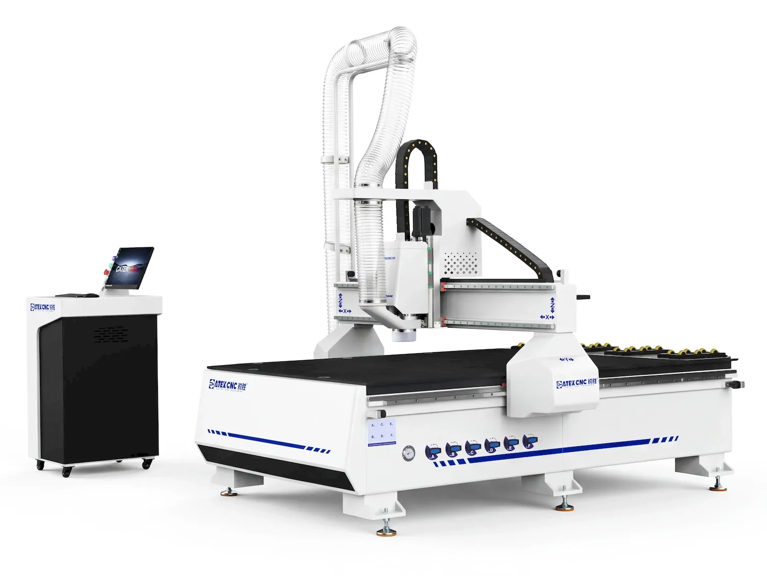
The Spire 1520 is a precision-engineered CNC router featuring a 1500×2000mm work area. As a custom-tailored model within the Spire Series, it comes integrated with a high-performance vacuum worktable and CATEKCNC's proprietary spindle and servo systems.
$4,800.00~$13,980.00

This cost-effective 4×8ft CNC wood router from the Spire Series features a dual-mode worktable that integrates vacuum hold-down and T-slot mechanical clamping on a single platform. This design offers greater flexibility for securing a wide range of workpieces across various machining requirements.
$3,980.00~$13,980.00
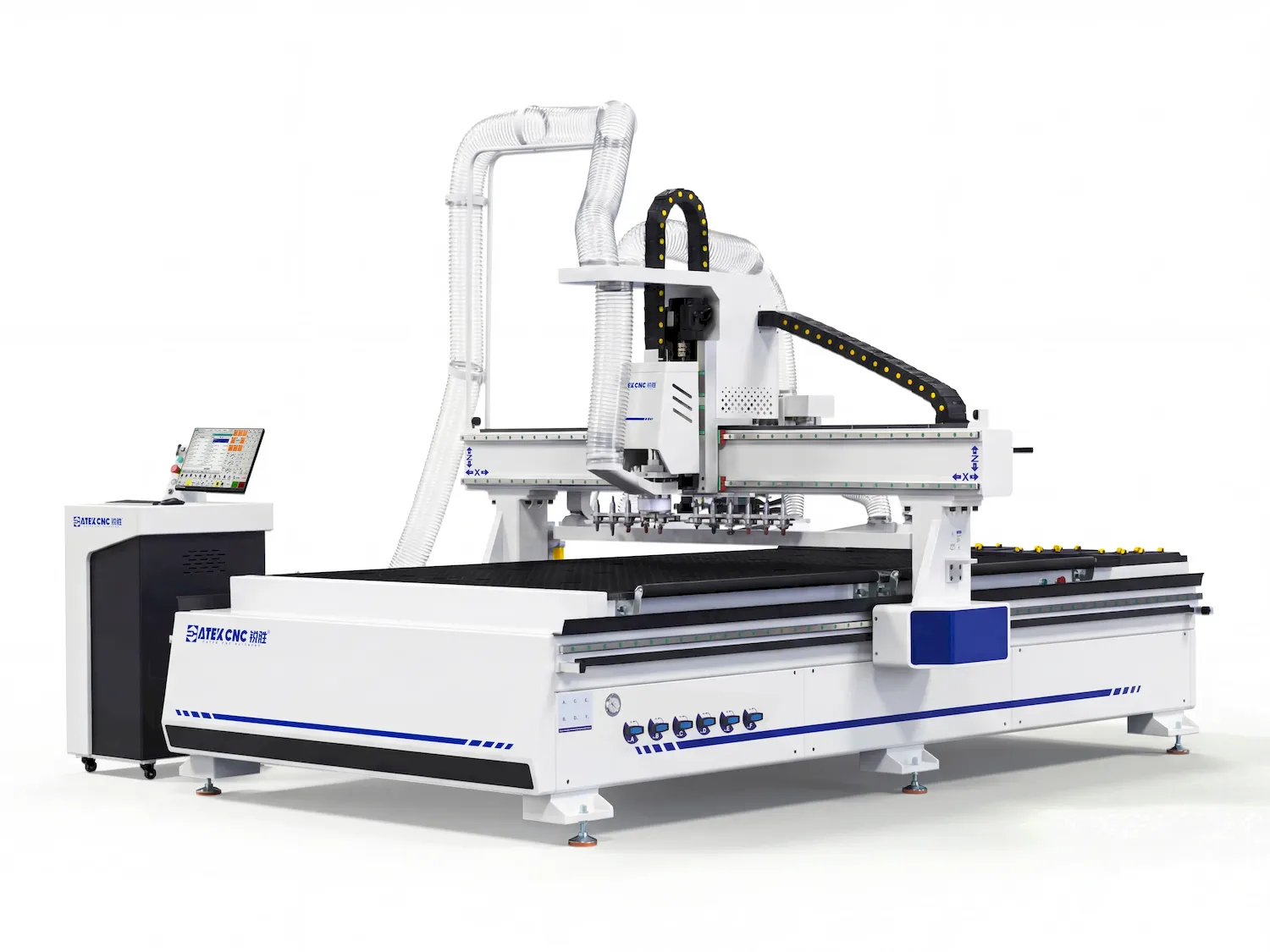
This is an 7x10ft (2100*3000mm) ATC CNC wood router from the Spire Series, highly adaptable to almost all machining sizes. It is equipped with a 9KW HQD ATC spindle, LNC servo system and control system, it delivers stable and efficient performance.
$13,800.00~$32,800.00